Application and Optimization of Plastic Molds in the Automotive Industry
Plastic molds are increasingly widely used in the automotive manufacturing sector, playing a crucial role in achieving lightweight, high-precision, and complex structural molding of automotive components. As the automotive industry advances rapidly toward electrification and intelligence, higher requirements are imposed on the performance, precision, and production efficiency of plastic molds. This article explores the current application status of plastic molds by combining practical cases in the automotive industry and proposes targeted optimization solutions.
1. Application Cases
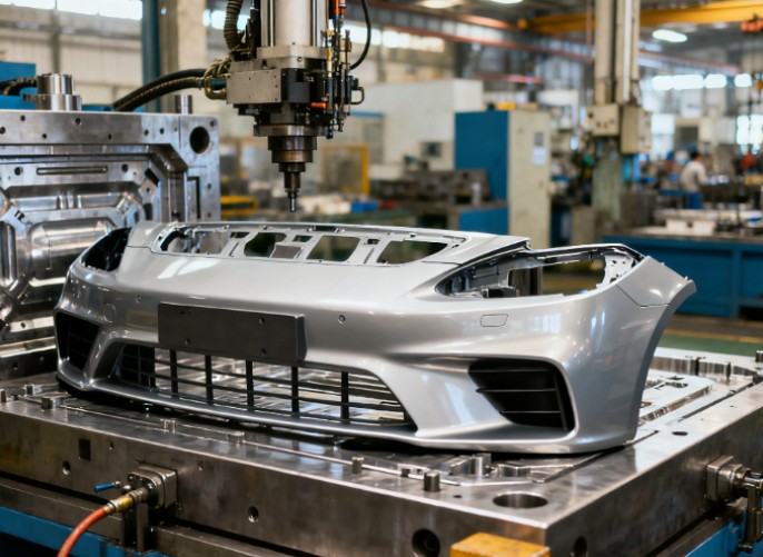
1.1 Application of Automotive Bumper Molds
Taking the bumper of a mid-sized SUV produced by a major automotive enterprise as an example, it is manufactured via injection molding using a polypropylene (PP) material formula combined with talc powder filling. The bumper mold is a multi-cavity hot-runner mold with 4 cavities. In actual production, the mold’s injection pressure is set to 80MPa, injection speed to 60cm3/s, holding pressure to 60MPa, holding time to 15s, cooling time to 25s, and the total production cycle is approximately 60s. Testing shows that the dimensional accuracy of the molded bumper reaches ±0.2mm, meeting the strict requirements of the automotive industry for bumper appearance and assembly dimensions. During the vehicle’s lifecycle, this mold has produced over 500,000 bumpers, with only 3 maintenance operations—mainly replacing locally worn inserts—demonstrating excellent mold lifespan and stability.

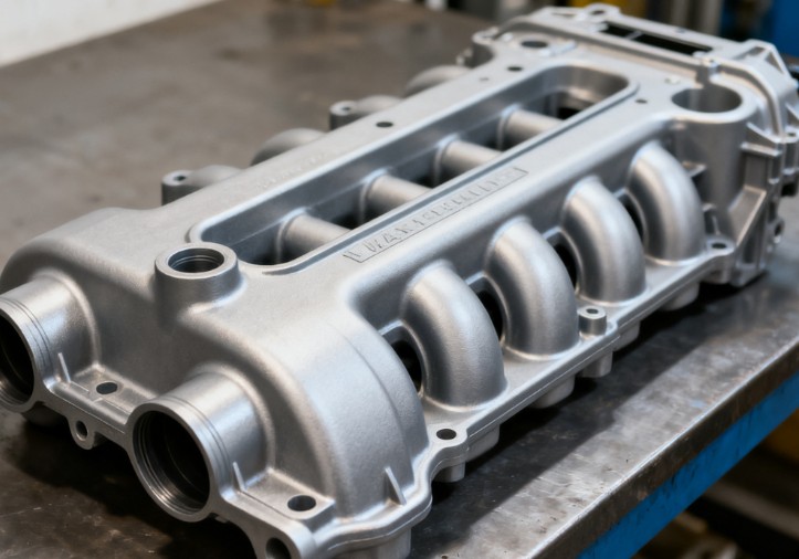
1.2 Application of Automotive Engine Intake Manifold Molds
The plastic intake manifold of an automotive engine uses glass fiber-reinforced nylon (PA6 + 30% GF) material, and the corresponding mold is a thermosetting injection mold (due to the material’s cross-linking reaction characteristics at high temperatures). The mold’s heating temperature is controlled at 85℃ to ensure material fluidity and curing effect. The injection pressure is 120MPa, injection speed 40cm3/s, holding pressure 90MPa, holding time 20s, cooling time 30s, and the production cycle is about 75s. In the airtightness test of the molded intake manifold, the leakage rate is less than 5mL/min under a pressure of 0.5MPa, fully complying with the sealing requirements of the engine intake system. Since its commissioning, the mold has produced 200,000 intake manifolds, and the surface roughness of the mold cavity remains below Ra0.4μm, ensuring the surface quality of the intake manifolds.
2. Existing Problems
2.1 Mold Design Issues
For molds of complex automotive components (e.g., automotive instrument panel molds), their structures include multiple buckles, grooves, and regions of varying thicknesses, making it difficult to design runner layouts and select gate positions. Unreasonable runner design may cause uneven material filling, leading to defects such as short shots and weld lines. For instance, due to improper gate position selection in the early instrument panel mold designed by an automotive enterprise, the edge area of the instrument panel was insufficiently filled, resulting in a scrap rate of 8%.

2.2 Mold Manufacturing Precision Issues
For precision plastic automotive components (e.g., automotive sensor housing molds), the required dimensional accuracy is ±0.05mm. However, in actual mold manufacturing, due to limitations in processing equipment precision and heat treatment deformation, the dimensions of some mold-forming parts fail to fully meet design requirements. Statistics show that the first-pass yield of sensor housing molds produced by a mold manufacturer is only 70%, requiring multiple mold repairs to meet precision standards, which increases mold manufacturing costs and lead times.
2.3 Mold Production Efficiency Issues
The automotive industry faces rapid changes in market demand, requiring high production efficiency of plastic molds. However, the cooling system design of some traditional plastic molds (e.g., automotive door panel molds) is not optimized, with unreasonable cooling channel layouts, leading to long mold cooling times and difficulty in further shortening the production cycle. Taking an automotive door panel mold as an example, the original cooling time was 35s, accounting for over 50% of the total production cycle, which restricted the improvement of production efficiency.
3. Optimization Solutions
3.1 Mold Design Optimization
Computer-Aided Engineering (CAE) software (e.g., Moldflow) is used to conduct flow simulation analysis on automotive component molds. Taking the automotive bumper mold as an example, Moldflow simulation is applied to optimize runner diameter and gate position, achieving more uniform material filling. Meanwhile, mold flow analysis is used to determine optimal process parameters such as injection pressure and speed, reducing the occurrence of molding defects. After optimization, the scrap rate of the bumper mold decreased from 5% to 2%.
3.2 Mold Manufacturing Precision Optimization
High-precision processing equipment (e.g., 5-axis machining centers) is adopted to improve the processing precision of mold-forming parts. For automotive sensor housing molds, machining centers with a precision of ±0.005mm are used to process cavities and cores. In addition, digital inspection technology (e.g., Coordinate Measuring Machines, CMM) is introduced to conduct 100% full-dimensional inspection of mold parts, ensuring mold manufacturing precision meets design requirements. Through these measures, the first-pass yield of sensor housing molds produced by a mold manufacturer increased to over 90%.

3.3 Mold Production Efficiency Optimization
The mold cooling system design is optimized by adopting conformal cooling channel technology. Taking the automotive door panel mold as an example, 3D printing technology is used to manufacture mold inserts with complex conformal cooling channels, making the cooling channels closer to the cavity surface and improving cooling efficiency. After optimization, the cooling time of the door panel mold was shortened to 20s, and the production cycle was reduced from 70s to 55s, increasing production efficiency by approximately 21%. At the same time, quick mold change technology (e.g., hydraulic quick mold change systems) is adopted to reduce mold change time and improve equipment utilization.
4. Conclusion
Plastic molds are widely used and critical in the automotive industry. Through the analysis of typical component mold application cases (e.g., automotive bumpers and engine intake manifolds), the current problems in mold application—related to design, manufacturing precision, and production efficiency—are identified. The optimization solutions proposed, combining technologies such as CAE simulation, high-precision processing equipment, and conformal cooling channels, can effectively improve the application level of plastic molds in the automotive industry, meet the evolving needs of the automotive industry, and provide strong support for the lightweight, high-precision, and efficient production of automotive components. With the continuous advancement of automotive industry technology, plastic mold technology will also continue to innovate and develop, further promoting the upgrading of the automotive manufacturing industry.
